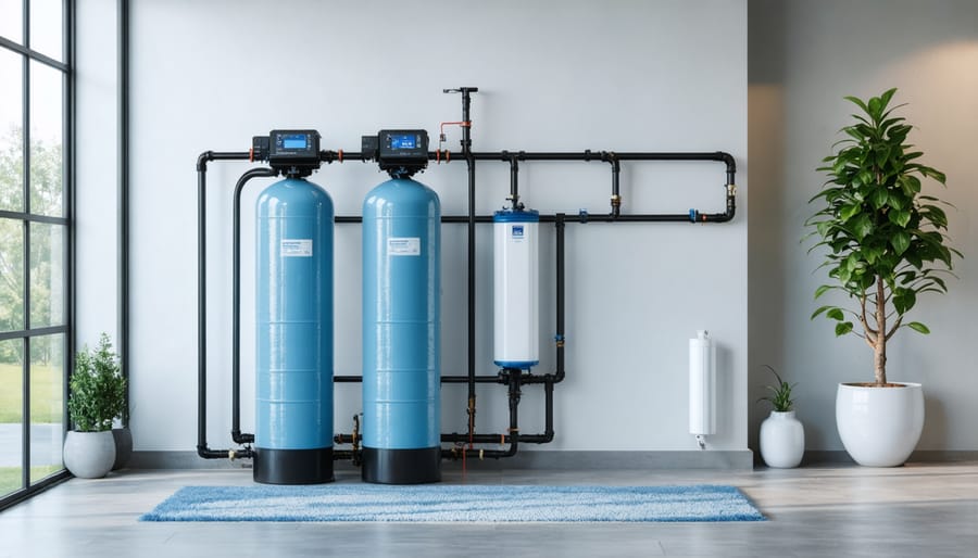
Locate your main water supply line where it enters your home—this marks the starting point for any water softener installation diagram. Before you invest in a professional installer or tackle this project yourself, understanding the visual blueprint of a water softener system empowers you to make informed decisions, avoid costly mistakes, and ensure your household enjoys mineral-free water for years to come.
Reading a water softener installation diagram might seem intimidating at first glance, with its array of pipes, valves, and connections, but these technical drawings follow logical patterns that anyone can decode. The typical diagram shows three critical connection points: the incoming hard water line, the outgoing soft water line, and the drain line for brine disposal. Like other water treatment systems, proper installation determines whether your investment delivers results or creates headaches.
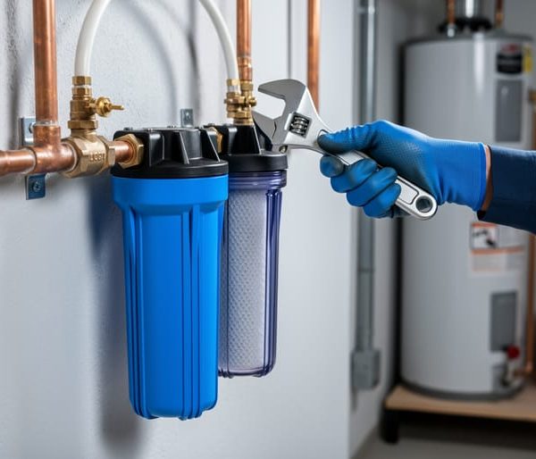
Position your softener near a drain and electrical outlet while maintaining adequate clearance for salt refills and maintenance access. The bypass valve—often represented in diagrams as three connected valves—serves as your safety net, allowing you to isolate the system without disrupting your home’s water supply during repairs or emergencies.
This guide transforms complex installation schematics into straightforward, actionable steps that respect both your time and intelligence. Whether you’re a DIY enthusiast or simply want to supervise professional work confidently, you’ll discover how proper diagram interpretation prevents the common pitfalls that compromise water quality and system longevity.
Understanding Your Water Softener Installation Diagram
Key Components Labeled in Standard Diagrams
Understanding the key components in a water softener installation diagram helps you confidently approach your installation project. These diagrams typically feature several essential elements that work together to create an efficient, eco-friendly water treatment system.
The **inlet and outlet connections** are your starting points—these show where hard water enters the softener and where softened water exits to supply your household. You’ll see these clearly marked with directional arrows indicating water flow.
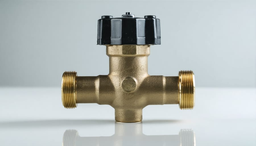
The **bypass valve** is a crucial component that allows you to temporarily redirect water around the softener during maintenance or emergencies. This three-way valve ensures you maintain water access even when your system needs attention, making it an important feature for uninterrupted household operation.
Your diagram will highlight the **drain line connection**, which removes mineral-rich wastewater during the regeneration cycle. Proper drain line installation prevents backflow and ensures efficient operation while minimizing water waste—an important consideration for environmentally-conscious homeowners.
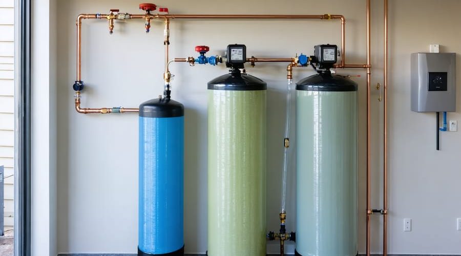
The **brine tank** stores salt solution used to regenerate the resin beads that actually soften your water. Diagrams show its position relative to the main unit and connection points for the brine line.
The **control valve** serves as your system’s brain, managing regeneration cycles and water flow. Modern electronic valves optimize salt and water usage, reducing environmental impact.
Finally, look for the **overflow connection**, which prevents brine tank flooding by safely directing excess water to the drain—a simple but essential safety feature protecting your home.
Common Symbols and What They Mean
Understanding installation diagrams becomes simple once you recognize the basic symbols. **Arrows** indicate water flow direction—following these helps you trace how water moves through your softener system from entry to exit. **Valve symbols** appear as various geometric shapes (circles, triangles, or squares) and represent control points where water flow can be stopped, diverted, or regulated.
**Pipe connections** are shown as lines meeting at junctions, with thicker lines typically indicating main water lines and thinner ones representing drain or overflow connections. **Solid lines** represent permanent pipe connections, while **dashed lines** often show optional or alternative routing paths.
**Directional flow indicators** (triangular arrows along pipes) confirm which way water should travel, preventing costly reverse-installation mistakes. You’ll also see **T-shaped symbols** marking bypass valves—essential for maintenance without shutting off your home’s entire water supply.
**Circle-with-X markings** typically indicate shutoff valves, crucial safety points in your system. By familiarizing yourself with these standard symbols before starting your installation, you’ll confidently navigate any manufacturer’s diagram and ensure proper water flow throughout your eco-friendly softening system.
Essential Pre-Installation Requirements
Location and Space Planning
Choosing the right location for your water softener is crucial for efficient operation and longevity. Your installation diagram will specify minimum clearance requirements—typically 10-12 inches on all sides—to allow for salt refills and future maintenance. This breathing room isn’t just about convenience; it ensures proper ventilation and prevents moisture buildup that could damage nearby walls or storage items.
Start by identifying your main water line entry point, as your softener should be installed as close as possible to where water enters your home. This strategic placement means all household water gets treated before reaching your fixtures and appliances. Your diagram will show the ideal positioning relative to this line.
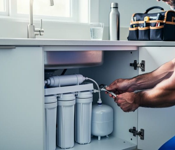
Next, verify drain access within 20 feet of your chosen spot. Water softeners need to discharge brine and backwash water during regeneration cycles, so proximity to a floor drain, utility sink, or standpipe is essential. Additionally, ensure a standard electrical outlet is within reach—most units require 110-volt power.
Before finalizing your location, consider accessibility for the 40-pound salt bags you’ll regularly add. A basement or garage location often works best, providing the necessary utility connections while keeping the system out of primary living spaces. Double-check that your chosen spot can support the unit’s weight when fully loaded with water and salt.
Tools and Materials You’ll Need
Before you begin your water softener installation, gather these essential items to ensure a smooth process. You’ll need basic plumbing tools including an adjustable wrench, pipe cutter or hacksaw, screwdrivers (both flathead and Phillips), and a measuring tape. A bucket and towels will help manage water spillage during setup.
For materials, purchase flexible supply lines appropriate for your plumbing system—either copper, PEX, or CPVC pipes depending on your existing setup. You’ll also need bypass valve fittings (often included with your softener), drain line tubing (typically ½-inch diameter), and appropriate connectors or compression fittings to match your pipe type. Don’t forget plumber’s tape (also called Teflon tape) for creating watertight seals on threaded connections.
Consider having a tubing cutter for cleaner cuts and pipe primer and cement if working with CPVC. A level ensures your unit sits correctly, which matters for proper regeneration. Finally, verify you have an appropriate drain location and electrical outlet nearby—most modern water softeners use minimal electricity, making them energy-efficient additions to your eco-conscious household. Having everything ready beforehand saves time and prevents mid-installation trips to the hardware store.
Step-by-Step Installation Following the Diagram
Connecting the Main Water Supply Lines
Connecting your water softener to the main supply lines is a critical step that directly impacts your home’s water quality. Before beginning, locate your main water shutoff valve and turn it completely off. Open several faucets throughout your home to drain remaining water and relieve pressure in the lines—this prevents messy spills during installation.
Your installation diagram will show two key connection points: the inlet (where hard water enters the softener) and the outlet (where softened water returns to your home’s plumbing). Most diagrams use blue arrows for inlet flow and red for outlet flow. Find the section of your main water line where you’ll make these connections, typically near your water heater or where the main line enters your home.
Using a pipe cutter, carefully cut into the main line at the location indicated in your diagram. Ensure cuts are straight and clean—uneven cuts can cause leaks later. Measure twice before cutting to avoid mistakes.
Next, install the bypass valve system, which allows you to temporarily redirect water around the softener during maintenance. Your diagram will show exactly how the bypass connects between the inlet and outlet ports. Most modern systems use push-fit connectors or compression fittings that don’t require soldering, making this eco-friendly upgrade accessible for DIY enthusiasts.
Connect the inlet pipe first, followed by the outlet. Hand-tighten all fittings initially, then use a wrench for a final quarter-turn. Avoid over-tightening, which can crack fittings. Double-check that all connections match your diagram’s flow direction—reversed connections will prevent proper softening and could damage your system.
Setting Up the Drain Connection
The drain connection is a critical component that safely removes brine solution and backwash water from your water softener system. Your installation diagram will clearly mark the drain line outlet on your softener unit—typically a small port measuring between ½ to ¾ inches.
Most importantly, you’ll need to establish an air gap between the drain line and your household drain. This air gap—usually a minimum of 1.5 to 2 inches—acts as a protective barrier preventing contaminated water from flowing backward into your softener. Think of it as an invisible safety shield that keeps your system clean and functioning properly.
When routing your drain line, ensure the discharge point sits lower than the softener’s drain outlet. Gravity does the heavy lifting here, eliminating the need for pumps while reducing energy consumption—a win for both functionality and eco-conscious living. However, avoid placing the drain too far below the unit, as excessive vertical distance can strain the system.
Secure your drain line with clips or fasteners every few feet to prevent movement during discharge cycles. A loose line can create noise, splash issues, or even disconnect entirely. Most diagrams recommend flexible vinyl or PVC tubing that resists the mildly corrosive nature of brine solution.
Finally, direct your discharge line into a floor drain, utility sink, or standpipe—never into a sealed drain without proper venting. This ensures efficient water removal while preventing pressure buildup that could damage your new water softening system.

Installing the Brine Tank and Salt Supply
The brine tank is your water softener’s fuel station—it stores the salt that regenerates the resin beads, allowing your system to continuously remove hard minerals. When reviewing your installation diagram, you’ll notice the brine tank positioned near the main softener unit, typically within 10-20 feet for optimal performance.
Start by placing the tank on a level surface away from direct sunlight, which can degrade plastic components over time. The diagram will show a brine line—usually a thin, flexible tube—connecting the tank to the control valve. Attach this line securely to both connection points, ensuring no kinks that could restrict salt solution flow.
Critical to proper function is the overflow drain line. Your diagram indicates where this safety feature connects, preventing flooding if the brine tank malfunctions. Route this line to a floor drain or utility sink, maintaining a visible air gap (typically 1-2 inches) between the line and drain opening. This eco-friendly feature protects your home while preventing contaminated water from back-flowing into your softener.
Before adding salt, verify all connections are watertight. Fill the tank with high-purity softener salt—avoiding rock salt which contains impurities that reduce efficiency and contradict sustainable water treatment practices. Most systems require 40-50 pounds initially.
Making the Electrical Connection
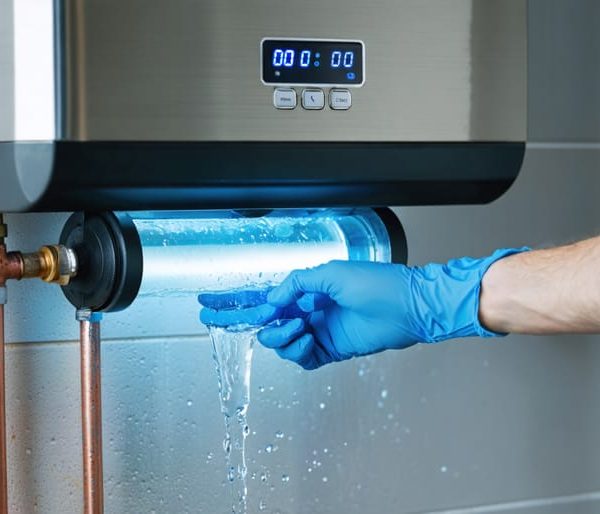
Most modern water softeners require a standard 120-volt electrical connection to power the control valve’s timer and regeneration system. Your installation diagram will specify the exact voltage requirements—always verify these before connecting.
Safety comes first: ensure the power is turned off at your circuit breaker before beginning any electrical work. The control valve typically plugs into a nearby GFCI-protected outlet, which safeguards against electrical shocks in moisture-prone areas. If an outlet isn’t available within three feet of your softener, you’ll need to install one—consider hiring a licensed electrician for this task.
Your diagram should indicate proper grounding requirements. Never bypass grounding connections, as they protect both you and your equipment from electrical hazards. The transformer (usually included with your softener) converts household current to the low voltage needed by the control valve.
Some eco-friendly models feature energy-efficient designs that consume minimal electricity—often less than a digital alarm clock. Keep electrical connections away from potential water exposure, even though most systems include waterproof components for added protection.
Troubleshooting Common Installation Diagram Confusion
When Your Home Plumbing Doesn’t Match the Diagram
Real-world plumbing rarely matches textbook diagrams perfectly, but don’t let that discourage you. Your home’s unique setup simply requires some thoughtful adaptation of standard installation plans.
Start by identifying your pipe materials. If you have PEX instead of copper, you’ll need different fittings and connection methods than shown in most diagrams. PEX requires compression fittings or crimp connections, while copper uses soldering or compression joints. CPVC pipes need solvent cement connections. Understanding your specific material helps you translate diagram instructions into appropriate techniques for your system.
Limited space presents another common challenge. Standard diagrams often show generous clearances that your basement or utility closet can’t accommodate. In tight spaces, consider compact water softener models or creative positioning. You might install the unit horizontally if vertical space is restricted, though you’ll need to verify your model supports this orientation. Some homeowners successfully create additional space by relocating nearby items or building simple shelving above the unit.
For non-standard plumbing configurations—like unusual pipe routing or multiple water heaters—sketch your actual layout alongside the standard diagram. Mark where connections align and where you’ll need modifications. This visual comparison helps identify necessary adapters, additional valves, or bypass loop adjustments. Many modern water softeners now feature flexible installation options specifically designed to accommodate diverse home situations, making adaptation easier while still delivering excellent water quality improvements for your household.
Understanding Flow Direction and Valve Orientation
One of the most critical—yet frequently misunderstood—aspects of water softener installation is ensuring water flows through the system in the correct direction. Most water softeners feature inlet and outlet ports clearly marked with arrows or labels indicating “IN” and “OUT.” The inlet connects to your home’s main water supply line, while the outlet sends softened water throughout your household.
Before connecting any pipes, locate these directional indicators on your unit. They’re typically found on the valve head or control unit. Installing your system backward prevents proper water treatment and can damage internal components, leading to costly repairs and wasted water—the opposite of sustainable living.
Additionally, bypass valves must be positioned correctly to allow water to circumvent the softener during maintenance or emergencies. These three-valve systems (two gate valves and one bypass valve) should align perpendicular to the pipes when in bypass mode and parallel when in service mode. Think of them like light switches—vertical for “on,” horizontal for “off.”
Taking a moment to double-check flow direction before finalizing connections saves both resources and frustration, ensuring your eco-friendly water treatment system operates at peak efficiency from day one.
Post-Installation Checks and Commissioning

Testing for Leaks and Proper Flow
Once your water softener is connected according to your installation diagram, it’s time to ensure everything works properly. Start by slowly opening the main water supply valve while keeping the bypass valve in the “bypass” position. This allows you to pressurize the system gradually and safely.
Next, carefully inspect each connection point marked on your diagram—inlet, outlet, drain line, and brine tank tubing. Look for any water droplets, dampness, or pooling that indicates a leak. Run your hand along pipes and fittings to detect moisture. If you find leaks, turn off the water, relieve pressure, and tighten connections as needed. Remember, hand-tight plus a quarter turn is usually sufficient for most fittings.
Now, switch the bypass valve to the “service” position to direct water through your softener. Open a cold water faucet and let it run for several minutes. The water should flow steadily without sputtering or pressure drops. Test the bypass valve by switching it back and forth—water should flow whether the softener is engaged or bypassed.
This systematic approach prevents water damage and ensures your eco-friendly water treatment system operates efficiently from day one.
Initial System Programming and Regeneration Cycle
Once your water softener is physically installed, it’s time to bring it to life through initial programming—a crucial step that ensures your system operates efficiently and sustainably for years to come.
Start by programming your control valve according to your household’s specific needs. You’ll need to input your water hardness level (measured in grains per gallon), household size, and daily water usage. Most modern control valves feature user-friendly digital displays that walk you through this process step-by-step. Don’t worry if this seems technical—think of it as setting a smart thermostat for your water system.
Next, manually initiate your first regeneration cycle using the control valve’s manual regeneration button. This initial cycle flushes out any manufacturing residues and primes your resin bed with sodium ions. You’ll hear water flowing through the system—this is normal and indicates everything is working as designed.
During this first cycle, check your drain line to confirm proper discharge. Water should flow freely without backing up, much like ensuring proper drainage in any eco-friendly home system. This verification prevents future issues and protects your investment.
Finally, monitor the complete cycle (typically 90-120 minutes) to ensure all stages complete successfully. Just like proper maintenance of other water treatment systems, this initial attention establishes a foundation for optimal long-term performance and water conservation.
Environmental Considerations and Water-Saving Tips
Proper water softener installation isn’t just about functionality—it’s also about minimizing environmental impact. Understanding your installation diagram helps you position components to maximize efficiency and reduce waste, which benefits both your household and the planet.
When following your installation diagram, pay attention to the brine tank placement and regeneration cycle settings. Modern water softeners can be programmed to regenerate based on actual water usage rather than fixed schedules, potentially cutting salt consumption by 25-40%. Position your brine tank in a temperature-stable location as shown in the diagram, since extreme temperatures can affect system performance and salt efficiency.
Consider these eco-friendly optimization tips during installation:
Use high-efficiency salt pellets rather than rock salt to reduce waste and improve regeneration efficiency. Your diagram should show the proper water flow direction—ensuring this is correct prevents unnecessary water waste during backwashing cycles.
Install a bypass valve as indicated in most diagrams. This allows you to divert water from the softener when soft water isn’t needed, such as for outdoor irrigation, extending resin life and conserving salt.
Monitor your softener’s salt-to-water ratio settings. Over-softening wastes salt and adds unnecessary sodium to wastewater. Many municipalities now offer guidance on optimal hardness levels for your area.
Finally, consider directing your brine discharge to landscaping areas that tolerate salt, rather than directly to sewers, where local regulations permit. This sustainable approach reduces environmental impact while maintaining the water quality improvements your household needs.
Understanding a water softener installation diagram might seem daunting at first, but with careful attention to detail and the guidance provided in this article, you’re well-equipped to tackle this home improvement project. Remember that these diagrams are designed to help you—not confuse you—and following them systematically ensures your system operates efficiently for years to come.
Proper installation is crucial for maximizing your softener’s performance and achieving the water quality improvement you’re seeking. When installed correctly, your system will reduce scale buildup, protect your appliances, and provide softer water throughout your home while minimizing environmental impact through efficient salt and water usage.
Always prioritize your specific manufacturer’s installation diagram over general guidance. While this article serves as a comprehensive reference to help you understand common components and installation principles, each system has unique specifications that must be followed precisely. Manufacturer diagrams account for their product’s particular design features, ensuring optimal performance and maintaining your warranty coverage.
If you encounter confusion or feel uncertain at any point during installation, don’t hesitate to consult with a professional plumber. Sometimes a quick consultation can prevent costly mistakes and give you peace of mind. With the right preparation, careful reading of your diagram, and attention to detail, you’re capable of achieving a successful installation that delivers lasting benefits for your home and family.